Pipe
Create Function
For creating a single pipe:
- create_pipe_from_parameters(*args, **kwargs)
If using a standard type:
- create_pipe(net, from_junction, to_junction, std_type, length_km, loss_coefficient=0, sections=1, text_k=0, name=None, index=None, geodata=None, in_service=True, type='pipe', **kwargs)
Creates a pipe element in net[“pipe”] from pipe parameters.
- Parameters:
net (pandapipesNet) – The net for which this pipe should be created
from_junction (int) – ID of the junction on one side which the pipe will be connected to
to_junction (int) – ID of the junction on the other side to which the pipe will be connected to
std_type (str) – Name of standard type
length_km (float) – Length of the pipe in [km]
loss_coefficient (float, default 0) – An additional pressure loss coefficient, introduced by e.g. bends
sections (int, default 1) – The number of internal pipe sections. Important for gas and temperature calculations, where variables are dependent on pipe length.
text_k (float, default None, will be set equal to the net ambient temperature) – Ambient temperature of pipe in [K]
name (str, default None) – A name tag for this pipe
index (int, default None) – Force a specified ID if it is available. If None, the index one higher than the highest already existing index is selected.
geodata (array, shape=(,2L), default None) – The coordinates of the pipe. The first row should be the coordinates of junction a and the last should be the coordinates of junction b. The points in the middle represent the bending points of the pipe.
in_service (bool, default True) – True for in service, False for out of service
type (str, default "pipe") – An identifier for special types of pipes (e.g. below or above ground)
kwargs – Additional keyword arguments will be added as further columns to the net[“pipe”] table
- Returns:
index - The unique ID of the created element
- Return type:
int
- Example:
>>> create_pipe(net, from_junction=0, to_junction=1,
>>>             std_type='315_PE_80_SDR_17', length_km=1)
For creating multiple pipes at once:
- create_pipes_from_parameters(*args, **kwargs)
If using a standard type:
- create_pipes(net, from_junctions, to_junctions, std_type, length_km, loss_coefficient=0, sections=1, text_k=None, name=None, index=None, geodata=None, in_service=True, type='pipe', **kwargs)
Convenience function for creating many pipes at once. Parameters ‘from_junctions’ and ‘to_junctions’ must be arrays of equal length. Other parameters may be either arrays of the same length or single values. In any case the line parameters are defined through a single standard type, so all pipes have the same standard type.
- Parameters:
net (pandapipesNet) – The net for which this pipe should be created
from_junctions (Iterable(int)) – IDs of the junctions on one side which the pipes will be connected to
to_junctions (Iterable(int)) – IDs of the junctions on the other side to which the pipes will be connected to
std_type (str) – Name of standard type
length_km (Iterable or float) – Lengths of the pipes in [km]
loss_coefficient (Iterable or float, default 0) – Additional pressure loss coefficients, introduced by e.g. bends
sections (Iterable or int, default 1) – The number of internal pipe sections. Important for gas and temperature calculations, where variables are dependent on pipe length.
text_k (Iterable or float, default None, will be set equal to the net ambient temperature) – Ambient temperatures of pipes in [K]
name (Iterable or str, default None) – Name tags for these pipes
index (Iterable(int), default None) – Force specified IDs if they are available. If None, the index one higher than the highest already existing index is selected and counted onwards.
geodata (array, shape=(no_pipes,2L) or (,2L), default None) – The coordinates of the pipes. The first row should be the coordinates of junction a and the last should be the coordinates of junction b. The points in the middle represent the bending points of the pipe.
in_service (Iterable or bool, default True) – True for in service, False for out of service
type (Iterable or str, default "pipe") – Identifiers for special types of pipes (e.g. below or above ground)
kwargs – Additional keyword arguments will be added as further columns to the net[“pipe”] table
- Returns:
index - The unique IDs of the created elements
- Return type:
array(int)
- Example:
>>> pipe_indices = create_pipes(net,
>>>                             from_junctions=[0, 2, 6],
>>>                             to_junctions=[1, 3, 7],
>>>                             std_type='315_PE_80_SDR_17',
>>>                             length_km=[0.2, 1, 0.3])
Component Table Data
net.pipe
Parameter |
Datatype |
Value Range |
Explanation |
name |
string |
Name of the pipe |
|
from_junction |
integer |
\(>\) 0 |
Index of junction at which the pipe starts |
to_junction |
integer |
\(>\) 0 |
Index of junction at which the pipe ends |
std_type |
string |
A selected std type for the pipe |
|
length_km |
float |
\(>\) 0 |
Length of the pipe [km] |
diameter_m |
float |
\(\gt\) 0 |
Inner diameter of the pipe [m] |
k_mm |
float |
\(\gt\) 0 |
Pipe roughness [mm] |
loss_coefficient |
float |
\(\geq\) 0 |
An additional loss coefficient which might account for e.g. bends |
alpha_w_per_m2k |
float |
\(\geq\) 0 |
Heat transfer coefficient [W/(m^2K)] |
qext_w |
float |
\(>\) 0 |
An additional heat flow entering or leaving the pipe [W] |
text_k |
float |
\(>\) 0 |
The ambient temperature used for calculating heat losses [K] |
sections |
integer |
\(\geq\) 1 |
The number of internal pipe sections |
in_service |
boolean |
True / False |
Specifies if the line is in service. |
type |
string |
Type variable to classify junctions |
net.pipe_geodata
Parameter |
Datatype |
Explanation |
coords |
list |
List of (x,y) tuples that mark the inflexion points of the pipe |
Physical Model
For both the hydraulic and temperature calculation mode, the main function of the pipe element is to calculate pressure and heat losses, respectively.
Hydraulic mode
The following image shows the implemented pipe model with relevant quantities of the hydraulic calculations:
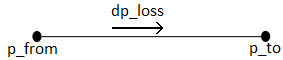
Losses are calculated in different ways for incompressible and compressible media. Please also note that for an incompressible fluid, the velocity along the pipe is constant. This is not the case for compressible fluids.
Incompressible media
The pressure loss for incompressible media is calculated according to the following formula:
Compressible media
For compressible media, the density is expressed with respect to a reference state using the law of ideal gases:
As reference state variables, the normal temperature and pressure are used by pandapipes. With this relation, also the pipe velocity can be expressed using reference values:
Inserting the equations from above in the differential equation for describing the pressure drop along a pipe results in the following formula, which is used by pandapipes to calculate the pressure drop for compressible media:
The equation for pressure drop also introduces a variable K. This is the compressibility factor, which is used to account for real gas behaviour.
After calculating the gas network, the pressure losses and velocities for the reference state are known. During post processing, the reference velocities are recalculated according to
The equations from above were implemented following [EH90].
Because the velocity of a compressible fluid changes along the pipe axis, it is possible to split a pipe into several sections, increasing the internal resolution. The parameter sections is used to increase the amount of internal pipe sections.
Friction models
Three friction models are used to calculate the velocity dependent friction factor:
Nikuradse
Prandtl-Colebrook
Swamee-Jain
Nikuradse is chosen by default. In this case, the friction factor is calculated by:
Note that in literature, Nikuradse is known as a model for turbulent flows. In pandapipes, the formula for the Nikuradse model is also applied for laminar flow.
If Prandtl-Colebrook is selected, the friction factor is calculated iteratively according to
Equations for pressure losses due to friction were taken from [EH90] and [Cer08].
The equation according to Swamee-Jain [SJ76] is an approximation of the calculation method according to Prandtl-Colebrook. It is an explicit formula for the friction factor of the transition zone of turbulent flows in pipes and is defined as follows:
Heat transfer mode
The following image shows the implemented pipe model with relevant quantities of the heat transfer calculations:

For heat transfer, two effects are considered by the pipe element:
The heat loss due to a temperature difference between the pipe medium and the surrounding temperature is calculated
An additional heat in- or outflow can be specified by the user
The heat losses are described by
according to [BS10]. If the default value of the sections parameter is changed, the resolution of temperature values can be increased.
Result Table Data
For incompressible media:
net.res_pipe
Parameter |
Datatype |
Explanation |
v_mean_m_per_s |
float |
The mean pipe velocity [m/s] |
p_from_bar |
float |
Pressure at “from”-junction [bar] |
p_to_bar |
float |
Pressure at “to”-junction [bar] |
t_from_k |
float |
Temperature at “from”-junction [K] |
t_to_k |
float |
Temperature at “to”-junction [K] |
mdot_from_kg_per_s |
float |
Mass flow into pipe [kg/s] |
mdot_to_kg_per_s |
float |
Mass flow out of pipe [kg/s] |
vdot_norm_m3_per_s |
float |
Norm volume flow [m^3/s] |
reynolds |
float |
Average Reynolds number |
lambda |
float |
Average pipe friction factor |
For compressible media:
net.res_pipe
Parameter |
Datatype |
Explanation |
v_from_m_per_s |
float |
The velocity at the pipe entry [m/s] |
v_to_m_per_s |
float |
The velocity at the pipe exit [m/s] |
v_mean_m_per_s |
float |
The mean pipe velocity [m/s] |
p_from_bar |
float |
Pressure at “from”-junction [bar] |
p_to_bar |
float |
Pressure at “to”-junction [bar] |
t_from_k |
float |
Temperature at “from”-junction [K] |
t_to_k |
float |
Temperature at “to”-junction [K] |
mdot_from_kg_per_s |
float |
Mass flow into pipe [kg/s] |
mdot_to_kg_per_s |
float |
Mass flow out of pipe [kg/s] |
vdot_norm_m3_per_s |
float |
Norm volume flow [m^3/s] |
reynolds |
float |
Average Reynolds number |
lambda |
float |
Average pipe friction factor |
normfactor_from |
float |
Normfactor to calculate real gas velocity at “from”-junction (only for gas flows) |
normfactor_to |
float |
Normfactor to calculate real gas velocity at “to”-junction (only for gas flows) |